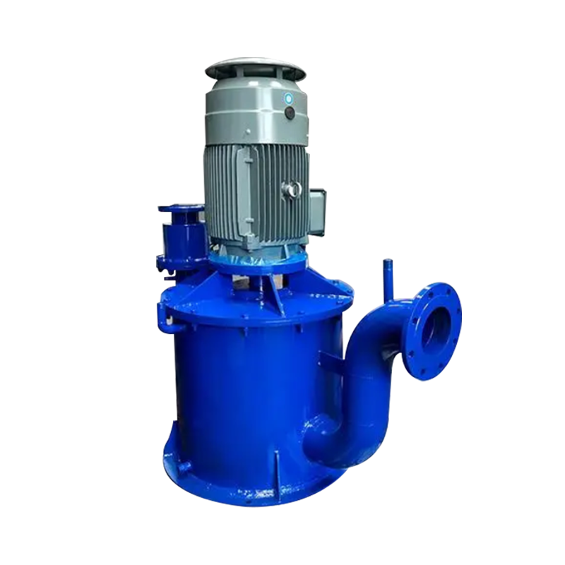
مضخة محرك مغناطيسي عالي درجة الحرارة (نماذج مبردة بالماء وبرودت الهواء)
Cat:المضخة المغناطيسية
نطاق الأداء: · القطر: DN25 ~ DN400 · معدل التدفق: حتى 2000 متر مكعب/ساعة · الرأس: ما يصل إلى 200 م · حد درجة ال...
انظر التفاصيلA self-priming pump is designed to evacuate air from its own suction line and casing before establishing normal liquid flow — without requiring manual filling or external vacuum assistance. In a conventional centrifugal pump, air in the suction line causes the impeller to spin without moving liquid, a condition called air-binding that generates no useful pressure and can damage the pump through overheating. A self-priming pump solves this by retaining a reservoir of liquid in its casing between operating cycles, which it uses to mix with and expel incoming air during the priming sequence until a full liquid column fills the suction line and normal pumping begins.
The priming cycle works through a specific physical sequence. When the pump starts, the retained liquid in the casing is thrown outward by the rotating impeller, creating a low-pressure zone at the impeller eye. This draws air in from the suction line. The air mixes with the recirculating liquid, forms an air-liquid mixture, and is expelled through the discharge. As air is progressively evacuated from the suction line, atmospheric pressure pushes liquid up from the source to fill the partial vacuum. Once liquid reaches the impeller and displaces the remaining air, the pump transitions to normal hydraulic operation. The entire priming cycle typically takes between 30 seconds and several minutes depending on the suction lift height, pipe diameter, and pump design.
The self-priming capability of these pumps depends on specific design features that distinguish them from standard centrifugal pumps. The most important is the liquid retention chamber — a volute or casing volume large enough to hold sufficient liquid after shutdown to initiate the next priming cycle. If the casing drains between cycles, the pump loses its self-priming ability and must be manually primed before the next start.
A check valve on the suction inlet prevents liquid from draining back to the source during shutdown, maintaining the casing's liquid reserve. Some designs use an internal recirculation port that routes discharge liquid back to the impeller inlet during priming, improving the air-liquid mixing efficiency and reducing priming time. The impeller itself is typically an open or semi-open design with wider passages than a standard closed impeller, accommodating the air-liquid mixture without losing hydraulic efficiency. The discharge check valve prevents reverse flow during shutdown and protects the pump from backpressure surges when the system restarts.
Self-priming pumps are not a single technology but a category that includes several distinct operating principles, each suited to different applications, fluid types, and performance requirements. Understanding the differences between types is essential to selecting the right pump for a specific installation.
The most widely used type, self-priming centrifugal pumps operate on the liquid retention and air-liquid mixing principle described above. They are produced in a broad range of sizes from fractional horsepower domestic units to large industrial models handling flows above 1,000 m³/h. Construction materials range from cast iron and stainless steel to polypropylene and PVDF for chemical service. These pumps are appropriate for clean liquids, mildly contaminated water, light slurries, and many chemical solutions. Their limitation is that standard impeller designs struggle with highly viscous fluids and heavily solids-laden slurries, which require specialized impeller geometries.
Trash pumps are a subtype of self-priming centrifugal pump specifically designed to handle liquids containing solid debris — rags, stones, sticks, and construction waste — without clogging. They use large-passage semi-open impellers with generous clearances between the impeller vanes and the volute casing. Trash pumps are essential in construction site dewatering, municipal flood response, and agricultural drainage where the pumped liquid contains significant suspended solids. Flow rates are typically high, but efficiency is lower than clean-water centrifugal pumps due to the open impeller design and larger internal clearances.
Rotary positive displacement pumps — including gear pumps, lobe pumps, and vane pumps — are inherently self-priming because their operating principle does not depend on liquid velocity to generate suction. The rotating elements create expanding and contracting cavities that mechanically displace fluid regardless of whether it is liquid or gas. This makes rotary self-priming pumps the correct choice for viscous fluids such as oils, adhesives, polymers, and food products where centrifugal pumps cannot develop adequate suction. They also handle entrained gas more tolerantly than centrifugal designs.
Peristaltic pumps move fluid by progressively squeezing a flexible hose or tube between rollers and a circular housing. Because the fluid is entirely contained within the hose and never contacts the pump mechanism, peristaltic pumps are inherently self-priming and suited to abrasive slurries, shear-sensitive biological fluids, and highly corrosive chemicals where other pump types would face rapid wear or material compatibility problems. They are widely used in chemical dosing, mining, and pharmaceutical applications. Flow rates are lower than centrifugal types, and hose replacement is a regular maintenance requirement.
The decision between a self-priming and a standard centrifugal pump comes down to the installation geometry and operational requirements. Standard centrifugal pumps must be installed below the liquid source — flooded suction — or must be primed manually or by a separate vacuum system before each start. This constraint is acceptable in fixed installations with reliable flooded suction, such as pump stations drawing from a wet well. It becomes a significant operational problem when the pump must be installed above the liquid surface, when the suction line may drain between cycles, or when unattended automatic restart capability is required.
| Factor | Self-Priming Pump | Standard Centrifugal Pump |
| Installation position | Above liquid source (suction lift) | Below liquid source (flooded suction) preferred |
| Unattended restart | Yes — automatic re-priming on restart | Requires flooded suction or external priming |
| Air handling | Tolerates air in suction line | Air-binds; requires air-free suction |
| Hydraulic efficiency | Slightly lower due to recirculation design | Higher efficiency at rated conditions |
| Initial cost | Higher for equivalent flow/head | Lower for equivalent flow/head |
| Portable/temporary use | Well suited | Not practical without flooded suction |
Selecting a self-priming pump requires matching the pump's performance characteristics to the system's hydraulic demands across three distinct operating phases: the priming cycle, the transition to full flow, and continuous operation. Each phase places different demands on the pump, and a pump sized only for steady-state flow may be inadequate for the priming conditions of the actual installation.
Suction lift is the vertical distance between the pump centerline and the liquid surface in the source tank or sump. Atmospheric pressure limits the theoretical maximum suction lift for any pump to approximately 10.3 meters at sea level, but practical limits are considerably lower due to vapor pressure, pipe friction losses, and the efficiency of the pump's air evacuation mechanism. Most self-priming centrifugal pumps have a rated maximum priming lift of 5 to 8 meters under ideal conditions — clean water, new suction hose, no leaks, operating at sea level. In real installations, derated lift values of 3 to 6 meters are more realistic planning figures. Specify a pump whose rated priming lift exceeds your installation requirement by at least 20% to provide margin for pipe aging, altitude effects, and warmer fluid temperatures that increase vapor pressure.
Flow rate (Q) and total dynamic head (TDH) define the pump's operating point on its performance curve. TDH is the sum of static head (elevation difference between source and discharge), friction losses in the piping system, and any pressure differential at the discharge point. The pump must be selected so that its duty point — the intersection of the pump curve and the system curve — falls within the pump's preferred operating range, typically between 80% and 110% of the best efficiency point (BEP) flow. Operating significantly left of the BEP causes recirculation and vibration; operating significantly right of the BEP causes cavitation, excessive shaft loading, and premature bearing failure.
The fluid's specific gravity, viscosity, temperature, and solids content all affect pump selection. Viscosities above approximately 50 cSt reduce the effective head and flow of centrifugal pumps and may require a positive displacement self-priming type instead. Elevated fluid temperatures increase vapor pressure, which reduces available NPSH and makes priming harder — specify pumps with lower NPSH requirements when handling hot liquids. For slurries and solids-laden fluids, specify the maximum solids size and concentration in weight percent; the pump manufacturer can then recommend appropriate impeller type and casing material.
Even a correctly specified self-priming pump will fail to prime reliably if the installation does not meet basic requirements. The suction line must be airtight — any air leak between the pump and the liquid source defeats the priming mechanism by allowing atmospheric air to enter faster than the pump can evacuate it. All suction pipe joints, valve packing, and flange gaskets must be in good condition and leak-free. This is particularly important for rubber hose assemblies where coupling seals degrade with age and UV exposure.
The suction line should be as short and straight as practical, with the pipe diameter sized to keep suction velocity below 1.5 m/s to minimize friction losses. Avoid placing gate valves, sharp bends, or reducers in the suction line where possible — each fitting adds resistance that increases the effective suction lift the pump must overcome during priming. A foot valve at the bottom of the suction pipe prevents liquid from draining back to the source and maintains the liquid column that the pump needs to sustain priming. Without a foot valve or a check valve at the suction inlet, the pump must re-evacuate the entire suction line on every restart, extending priming time and increasing wear on the air-handling components.
Understanding the most frequent causes of self-priming pump failure helps operators and maintenance teams prevent problems before they occur rather than diagnosing failures after they happen.
")
نطاق الأداء: · القطر: DN25 ~ DN400 · معدل التدفق: حتى 2000 متر مكعب/ساعة · الرأس: ما يصل إلى 200 م · حد درجة ال...
انظر التفاصيل
1. نطاق أداء المضخة الكيميائية من نوع CZ (وفقًا لنقطة التصميم) التدفق: س 1.6-1500M3/ساعة المصعد: H 5-125m ضغط العمل: P أقل من ...
انظر التفاصيل
1. نظرة عامة على مضخة العملية الكيميائية HJ HJ مضخة العملية الكيميائية المقاومة للتآكل هي مضخة الطرد المركزي من أحادي الطرد من أحادي الطابق....
انظر التفاصيل
1. نظرة عامة تم تصميم مضخات عملية ZA و Zao البتروكيماوية وفقًا لمواصفات AP1610 و VDMA24297 (خفيفة/متوسطة). 2. نطاق التطبيق هذه...
انظر التفاصيل
FB المضخة الكيميائية من الفولاذ المقاوم للصدأ تتمتع بمزايا الأداء الموثوق ، وختم جيد ، ومظهر جميل ، وسهولة الاستخدام والصيانة .
انظر التفاصيل
نظرة عامة على مضخة FSB fluoroplastic تم تصميم مضخة سبيكة FSB-type fluoroplastic وفقًا للأبعاد القياسية الدولية. يتم دمج جسم المضخة عضويا مع ...
انظر التفاصيل
تنقسم مضخة زيت نوع AY إلى شكلين هيكليين: نوع ناتئ أحادي المراحل ، ونوع ناتئ من مرحلتين ، ونوع ناتئ مزدوج المرحلتين ، ونوع مرحلتين مزدوجًا ونوعًا من...
انظر التفاصيل
تعتمد مضخة تداول المياه الساخنة HPK على التكنولوجيا الحاصلة على براءة اختراع لمضخة الطرد المركزي للسرعة المنخفضة ، والتي تم تطويرها على أساس امتصاص...
انظر التفاصيل
مضخة الصحافة المرشح عبارة عن مضخة مركزية رأسية ومرحلة واحدة ومرحلة واحدة ، من نوع الطرد المركزي من نوع الكابولي ، مصممة بشكل مبدئي على أساس نظرية ا...
انظر التفاصيل
تم تصميم مضخة إزالة الكبريتات الطويلة من نوع التحويل على وجه التحديد لتطبيقات الحوض تحت الأرض في أنظمة إزالة الكبريتات غاز محطات الطاقة ، والمعروفة...
انظر التفاصيلCopyright © Jiangsu Feixiang Pump Co. ، Ltd. All rights reserved. المضخات الكيميائية المصنعة
